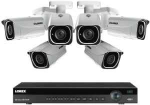
This is my review for installing a Lorex 4K IP Camera System. Specifically I have model 4KHDIP86, which is described as “4K Ultra HD IP 8 Channel NVR System with 6 Outdoor 4K 8MP IP Cameras, 130FT Night Vision, 2TB Hard Drive.” The cameras with this system are model LNB8111. The Network Video Recorder (NVR) is model NR908X, or specifically NR9082 with the 8-channel configuration. (See Amazon.)
For details on the technology and the features of this system, please refer to the product documentation. Here I provide recommendations on installing this particular system. In a subsequent blog post, I will review its features. Hopefully my experiences will help if you are considering this system, or in general, any Internet Protocol (IP) camera system.
I chose this technology because Internet Protocol (IP) cameras use Power Over Ethernet (PoE). That means there is only a single Ethernet cable that connects to the camera and it provides both power and data transfer. IP cameras are more “connected,” meaning you can access them easier over a local or remote network connection. And, they seem to offer many more features.
Due to the 4K bandwidth (each camera is 8 Megapixels), the connection is a wired connection. A wireless interface cannot currently handle such bandwidth.
Placement
Decide carefully where you want to place the NVR. The fan is noisy and runs continually. It is variable speed, and it will run faster (and louder) as the NVR gets hotter. The instructions recommend not placing it in an enclosed area. I recommend against locating it in a bedroom or home office. The constant whir is distracting. A closet would be ideal, but you must have a power outlet and a connection to your router, and of course an optional monitor for the NVR, and Ethernet cables that run to the cameras.
I wanted the option to view my security cameras on my TV in the family room. It therefore had to be close to the TV in order to connect the HDMI cable. If you locate the NVR some distance from your TV, I’m not sure how long an HDMI cable can be, both in terms of cost and signal strength. Luckily my TV credenza has a shelf enclosed by a glass door, and a vent hole. That has cut the fan noise to something tolerable, and it doesn’t seem to make the NVR run hotter.
Rather than connecting to a TV, you might consider just keeping a tablet computer in the family room. It can be simpler to pick up the tablet to view your security cameras rather than switch the source of your TV over to the NVR. But I like to view all the cameras on a big screen TV.
Although my TV has a picture-in-picture (PIP) feature, it only works with the antenna or cable, not the HDMI ports. So if you’re hoping to use PIP, check that your TV supports other inputs.
You will want to keep your NVR connected to the Internet at all times. This allows you to view security cameras from your PC and tablet from anywhere in your home. You can also take advantage of the Lorex Cloud or Lorex Secure apps to view your cameras from outside your local network.
My Internet router is in another room. I had to run a separate Ethernet cable between my router and the NVR in the family room. Plan to run that cable through your walls and through your attic or crawlspace, in addition to running the camera cables. Include wall jacks, boxes and covers in your plan, if needed.
If after a while you change your mind and want to move your NVR to a different location, you don’t need to re-route all your camera Ethernet cables. Purchase a Power Over Ethernet (PoE) switch and use it in place of the NVR. Plug all the camera Ethernet cables into the switch and connect the switch to your router. After you move the NVR to a different location, also connect it to your router. It will find and use your cameras on the local area network.
The drawback here is you will use another Ethernet port on your router. Most routers have only a few. You will also need an Ethernet connection wherever you relocate your NVR. You may need to run another Ethernet cable drop for it.
Running the Camera Cables
In my case, all my household electrical wiring is run through the attic. It was easy enough to run the Ethernet camera cables through the attic too. Unroll and unfurl each cable in your house before taking them up to the attic. I unrolled each cable one at a time and went back and forth a few times twisting the cable to get as much of the curl out as possible. It helps if the cable ends can freely twirl as you go along. I then wrapped each cable on a spool I had already made to store my electrical extension cords.
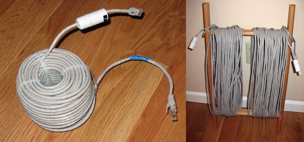
Be sure to number each cable now, so you know what port to plug into and where to route the cable once you’re in the attic. Don’t try to run two cables at once in the attic or they’ll get hopelessly intertwined.
Unfortunately my TV is against an exterior wall. Drilling a hole downward through the wall’s top plate will be almost impossible. The angle of the roof where it intersects with the top plate will likely be too narrow. You won’t be able to get close enough to it from inside the attic, let alone have room to operate a drill, even when using a right-angle chuck attachment.
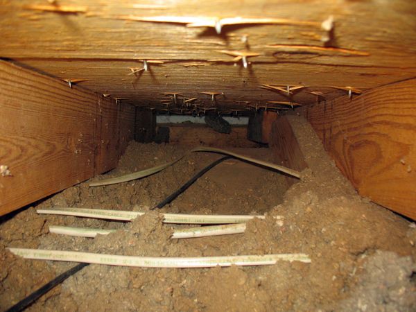
Here I found the exact spot in question from inside the attic. Electrical wires for the outlet behind my TV go down through the top plate on the left. To the right is the old coax cable for cable TV service. The two outlets are separated by a wall stud. That means the rafters meet the top plate between the wall studs. This is about as close as I can get to it, except I could probably stretch my arm to reach the top plate. It would be hard to see and to fit or maneuver a drill in that tight area.
Plan A: Drilling Upward
My first plan was to drill upward through the top plate from inside the wall. There are numerous problems with this method and I strongly recommend against doing this.
I first cut a hole the size of an outlet box in the wall behind the TV. The wall stud that separates the electrical box and the cable outlet box are on the right. The nearest wall stud to the left is 16 inches away, which I marked with masking tape. I made a cutout for the new junction box using a box cutter, so the left side of the box is against the wall stud. I knew that if I drilled straight up along the stud, the hole would come out the top plate exactly between the rafters. In other words I wouldn’t be drilling upward through the top plate and then directly into the rafter.
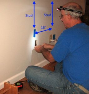
I used a flexible drill bit system commonly used by electricians. (See for example Southwire 54” Flexible Installation Kit, model FQCKIT at Amazon.) In the following picture, they are drilling downward, whereas I was drilling upward. However, I think such kits are intended for drilling holes sideways, or downward a short distance from the access hole. I wanted to avoid cutting an access hole in the drywall near the top of the wall. Although I could patch it over again and repaint the wall, it is difficult to make it look like it was never there.
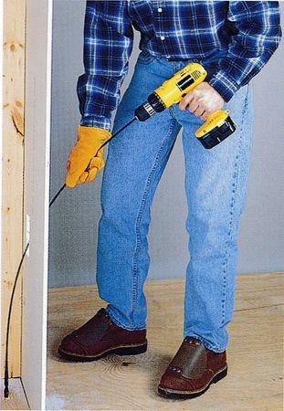
I had to use an additional 54” extension. Be careful. If your wall is taller than 8 feet you may need additional extensions. The outlet box hole is up off the floor, but you still need to attach the extension rod to your drill and have enough rod to make the bend upward. I had several problems.
First the insulation in the wall made it difficult to get the drill bit up to the top plate. I covered the bit with a piece of paper in the shape of a cone. That allowed me to slip past the insulation and the paper was promptly chewed to pieces when I started to drill into the top plate. The caution here is, don’t tape the paper to the drill bit, or the shavings from the drill bit won’t be expelled as they should.
Second, if you reverse the drill and back the drill bit out too far, you will undoubtedly start another hole the next time you go forward. It is almost impossible to continue drilling the same hole. Unfortunately the drill bit kit I used came in three sections. The connection to the drill chuck was just outside the outlet box hole. It twisted and broke the extension shaft.
If you use this method, ensure you have an ample length of the extension rod sticking out of the wall such that the joint or connection between extension rods is not within the sharp bend upward. The joint on my extension was in the curve and the torque was simply too much.
Third, the wall’s top plate will likely be a double top plate, meaning two 1.5 inch boards together for a total thickness of 3 inches. It is unlikely you will be able to drill through that much material without the drill bit bogging down. If you reverse it too far before going forward again, you risk starting another hole altogether.
Fourth, even if you successfully drill up through the top plate, you will probably need more than one hole. I used a 3/4” bit. For some reason I didn’t consider the thickness of all six Ethernet cables together. I thought I could tape each cable together with one connector slightly behind the next, to make a relatively narrow grouping. But even so, trying to fish six cables through a 3/4” hole would be problematic. If you are drilling through the top plate of an interior wall, you will likely be able to drill a few holes downward from the attic, without a problem.
Plan B: Under the Soffit
Luckily I had another plan I knew would work. I could remove the plywood soffit from the roof overhang outside the wall in question. The top plate and several inches of the wall outside are easily accessible from under the soffit. Removing the soffit will be difficult. It is nailed and caulked. Luckily I had replaced this particular panel years ago and used screws rather than nails. When I removed the original panel, I had to pry the panel down to pull out the nails. Since I was replacing it, I cut additional holes in it to get better access using a pry bar.
Once off, I simply cut the foam sheathing from the outside and ran the Ethernet cables around the outside of the top plate, not through it. (See blue arrow in following diagram.) I then patched the insulation and covered the wires with more insulation.
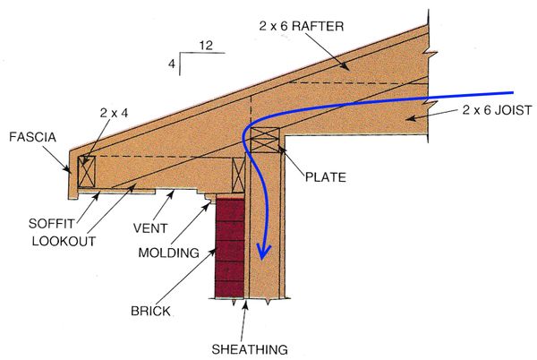
By the way, after removing the soffit, I found my drill bit from when I had tried to drill upward through the top plate from below. The bit bogged down and the extension rod broke, leaving the bit and most of the extension rod inside the wall. It would have been lost forever had I not been able to access it through the outside soffit. Lesson learned.
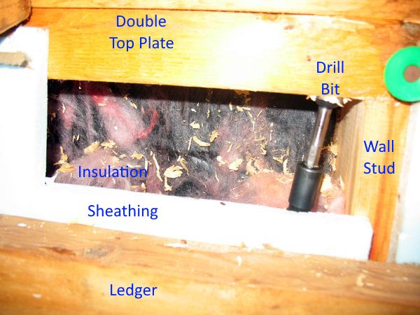
This photo shows the foam sheathing cut away and the inside of the wall with the top plate at top. The drill bit only made it through the first thickness of top plate. I had to back it out using a wrench. This method was doomed from the start.
Wall Plates for Camera Cables
There are options for managing six or more Ethernet cables coming out of the wall. One is an outlet box cover that has multiple RJ45 jacks. You simply plug each camera cable into a jack from the back of the plate. You then need a separate Ethernet patch cable for each camera to plug into the wall and run to the NVR. The jacks and extra cables are expensive, and you might not have enough room if you want to expand the number of cameras later.
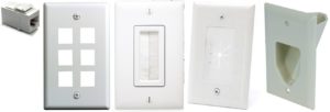
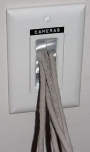
I chose a cable access wall plate. (See for example Legrand WP1014-WH-V1 at Amazon.) It has a rectangular opening with short bristles like a brush. All the Ethernet cables simply slip through the single opening and then plug directly into the NVR. I was impressed with the bristles maintaining their shape. It makes the opening neater. There are a couple other options. One has a star pattern of slits in flexible plastic. The other is an opening with a cone that directs the cables. I didn’t think they would look as good.
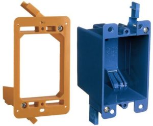
If your cables come out of an exterior wall, I recommend using a single-gang electrical box. (See Amazon.) Normally you would use a low-voltage “box” that is nothing but an open frame, which gives you something to attach a wall plate. (See Amazon.) However it’s possible for critters like mice to get inside walls and possibly crawl out the cable access wall plate slot. A closed electrical box would prevent that.
Mounting the Cameras
I chose to mount the cameras to the underside of the soffit rather than against a vertical wall. My soffit is plywood. If you have vinyl, you’ll probably need more support behind the soffit panel in order to have something to screw into. Perhaps you’ll have a “lookout” near where you want to mount a camera. These are usually 2x4s perpendicular to the house that run from the house to the end of the rafter.
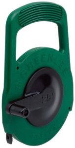
If you are uncertain where to mount a camera, open up a nearby soffit air vent cover. Run a fish tape up into the attic, tape on the Ethernet cable, then pull the fish tape back out. Plug in the camera and hold it by hand in various locations. Use the Lorex Cloud application on a tablet computer while you’re on the ladder. Less than a minute after you connect the camera, you’ll see exactly what it sees and you can find the perfect spot.
A fish tape is a good investment for this project. I’ve used this Greenlee tape for many projects over the years. (See Amazon.)
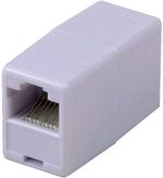
Alternatively, you can connect two 100-foot Ethernet cables together using an in-line coupler. (See Amazon.) Connect one cable end to your NVR and the other to your camera. Then just walk the camera outside, or through an open window, around your house and up the ladder. 200 feet of cable should be plenty to determine the best camera position before you actually route it through your attic and wall.
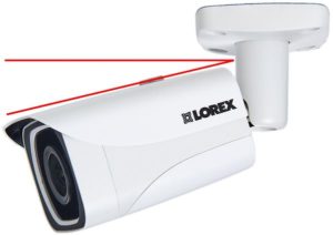
You’ll want to position it to avoid having downspouts, spotlights, or too much of the soffit in the field of view. The camera base allows you to orient the camera in all directions (roll, pitch, yaw) for a level view of any terrain. You will see a slight fish-eye effect. A straight street may appear slightly bowed, or high in the middle and curved at each end. The camera base does have a limit. If you choose a downward angle of view, you cannot position the camera to view higher than horizontal.
Side by Side
To cover a long expanse of the house, I mounted two cameras side-by-side in the middle of the expanse, rather than one camera at each corner of the house. One camera points one direction and the other in the other direction. The cameras have an 88-degree field of view, which together is slightly less than 180-degrees. But, I can capture each corner of the house and there is sufficient overlap in the field of view directly outward, perpendicular to the house.

This photo shows two separate camera views side-by-side. The left and right sides show both corners of the house. The red lines in the middle show the area overlapped by both cameras. The cameras are oriented slightly differently so the overlap is not uniform. The views are intentionally blurred for privacy.
The cameras are mounted next to each other with a 2-inch gap between the bases. I chose a spot centered between two windows. That way I can see all the window sills along the house. I mounted the camera 2 inches from the vertical outside wall (frieze board), which is out of the weather as much as possible. Don’t mount them closer than 2 inches or you won’t be able to use a screwdriver to adjust the mounting bracket to properly position your camera. I used a stubby screwdriver for that, but you can also use a right-angle screw driver. Just consider how a screwdriver will fit when deciding where to mount the camera.
I used a 1-inch spade bit to drill the hole to accept the Ethernet cable and the cable connector cover. The template supplied with the camera implies you should drill a larger hole, but 1-inch works fine. You’ll also want to pre-drill holes for the four mounting screws, then run all the screws in and back out before trying to screw in the camera base. It makes it much easier to install them when working overhead.
Send your fish tape upward through the hole and up into the attic. Then go up in the attic and tape the cable to the fish tape. Back outside, pull the fish tape out, which guides the cable out through the hole.
On the Corners
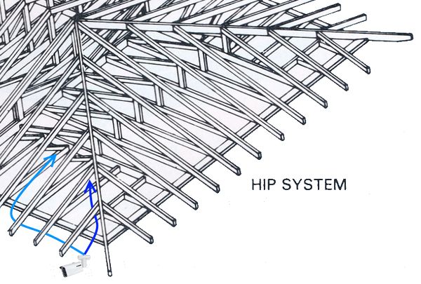
If mounting a camera at an outside corner of a soffit, especially if you have a hip roof, the rafters come down at such an angle from both directions, that it is almost impossible to get a fish tape up from a camera mounting hole into the attic. (See the dark blue line in the diagram below). It’s not worth trying to squeeze into that corner from inside the attic either.
Instead insert the fish tape up into the attic from a nearby soffit air vent hole. Attach the cable from inside the attic, then go back outside and pull the cable out the vent hole.
Now insert the fish tape up into the camera mounting hole and feed it over to the soffit air vent hole. Attach the cable again and pull it over to and out the camera mounting hole. (See the light blue line.) Much easier.
Backer Rod
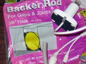
The camera base has a hole to accept the thickness of the cable in case you flush-mount the camera. Since my cable runs directly behind the base, that would leave an empty hole for bugs to enter. (We have mud dauber wasps here that fill every nook and cranny with mud for their nests.) If you mount the base close to a vertical wall, you won’t be able to get a caulk gun to fit afterwards. I filled the hole with a 1-inch length of backer rod, before I installed the camera base. (See Amazon.)
Final Adjustments
To make your final camera adjustments, use the Lorex Cloud application on a tablet computer while you are next to the camera. It shows exactly what the camera sees and you can fine-tune its orientation and tighten the set screw.
Sir,
I too bought a Lorex 4K NVR package. I purchased the 16 CH system with 8 IP cams. Would appreciate the opportunity to pick you brain on the record settings you chose for your system. I’m trying to find the right blend of quality vs. retention period. I did upgrade to two 6TB Western Digital Purple drives. Please email me.
Thanks,
Matthew