The power goes out occasionally. Sometimes it’s for an hour or two, and sometimes it’s several hours. During tornado outbreaks, we’ve been a week without power. We decided to invest in a portable generator rather than install a standby generator and its associated automatic or manual transfer switch. Obviously the standby generator is a better option, but realistically the power doesn’t go out that often, maybe once or twice a year. It didn’t seem to justify the cost.
A portable generator is more of an emergency use situation. It’s enough to keep the refrigerator and freezer running so our food doesn’t spoil. It’s as inconvenient as camping though, because we have to plug and unplug the microwave, toaster, coffee maker, and so on.
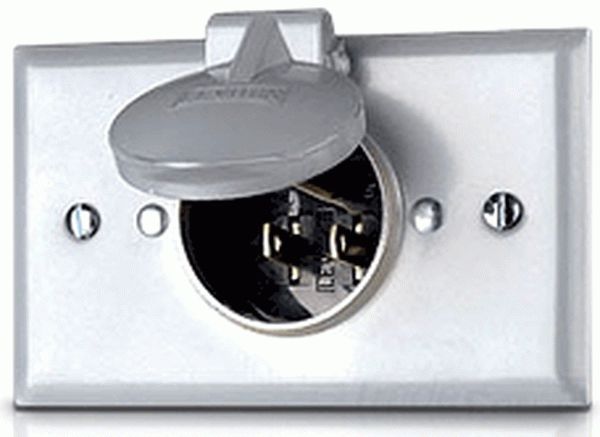
Another inconvenience is the extension cords that come in from outside, through an open door or window. Not only is that a security issue if the generator must run overnight, but it’s not weatherproof. To solve the problem I installed an inlet box on the outside of the house and wired it to an outlet centrally located in the kitchen. From there we simply run another extension cord between appliances.
These are the steps I took to install a generator inlet box on my house. Your situation will be different, but hopefully you’ll get some useful ideas. Keep in mind this is a simple substitute for running extension cords through open doorways for a small Honda EU2000i portable generator. I don’t address “generator inlet” boxes that are rated for more wattage and therefore have a different blade configuration, and require special extension cords.
You can download these steps. You will be prompted for a user name and password. The user name is Guest and the password is inlet.
https://home.iSeeAncestors.com/access.php?file=014163.pdf
There are many factors that influence where to mount an inlet box. You may have brick, or wood or vinyl siding. You may want to run wiring up to the attic or down to a crawlspace, or straight into an interior wall. I mounted the inlet box on an exterior brick wall and routed the wiring up to my attic.
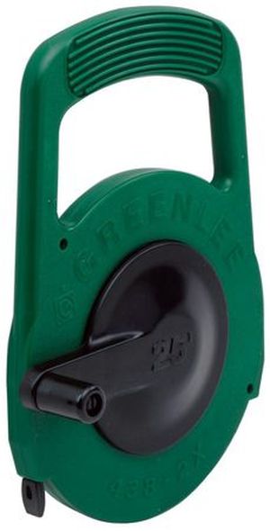
I can also remove a wood panel under the soffit of my house to gain easy access to the top of the brick wall. I saw where the studs are located, and I used a metal fish tape to probe all the way down the inside of the wall to ensure there were no obstacles. I found a good spot to drill through the brick.
If you cannot remove a soffit panel, you’ll have a much harder time locating the wall studs in relation to a spot outside the house. You’ll probably have to use a stud finder and measure carefully both inside and outside. It will also be more difficult to fish the wiring down from the attic inside the wall. In most houses the angle where the roof contacts the wall’s top plate is so acute you won’t be able to drill any holes or route any wiring in that area.
Exterior Inlet
I chose to mount an outdoor electrical box on the surface of the brick and drill a small hole through the brick for the wiring. If you do this, choose an inconspicuous place where it won’t get bumped, like a corner. A better option would be to chisel out half of one brick and insert an electrical box so it’s flush to the wall. But I’ve never had much luck mixing the right color and consistency of mortar, so I didn’t think that would end well for me.
I have spare bricks and I was able to measure one to determine the best place for a hole. The center of one of three voids in a brick was 1-3/4 inches from the edge. I applied masking tape to the brick and marked the center point for the hole. I placed the electrical box over the mark and leveled it. I also made sure the tabs where I would eventually install masonry screws lined up on the mortar lines. Its best to drill those holes in the mortar and not the brick itself. I drew a circle inside the conduit hole and onto the masking tape.
For extra stability and to avoid scuffing the wire, I used a 1/2-inch threaded PVC pipe nipple, also called a riser, that was 4 inches long. It is 3/4 inches in outside diameter. I centered it over the circle I marked and traced it’s circumference. That’s the size of the hole to drill through the brick.
I only have small masonry drill bits. Although a 3/4-inch bit would be best, I couldn’t justify $30 for a one-time use. Therefore I drilled three holes spaced evenly within the circle I drew. Then I used a 3/4-inch and a 3/8-inch cold chisel to gently chisel out the hole so it was 3/4 inches in diameter all the way through the brick. The secret here is to use short, gentle taps with a small sledge hammer. Don’t try to pound through a lot of brick at once or you’ll split it. (Yes, I practiced first on a spare brick and it fractured.) Note the voids in the brick will probably have some mortar in them from when they were laid.
My original plan was to fish the wiring up through the gap between the brick wall and the outside of the interior stud wall. There’s usually a 1-inch gap there. But one inch really isn’t enough space to maneuver wiring, plus there can be a lot of mortar that oozes out in between the bricks that further restricts the gap. I couldn’t get a fish tape down very far.
Once through the brick, I drilled a 1/2 inch hole through the insulation sheathing on the interior stud wall. If it’s living space, there’s probably insulation batting between the studs. You’ll want to fish the wire down outside that batting, but inside the foam sheathing, so you don’t penetrate the main insulation in the wall.
In my case I chose my garage wall. It has the foam sheathing, but no insulation batting between the studs. It was much easier to fish the wire down. To do that, I tied a small length of nylon string to the end of my metal fish tape. I then tied a few washers on the string. I pushed the fish tape down the inside of the wall from the soffit and poked a small retrieval magnet through the hole I drilled in the brick. I caught a couple washers and pulled the string out, which gave me enough slack to pull the stiffer metal fish tape down, and out through the hole.
I then tied a long length of doubled nylon string to the fish tape and pulled it back in through the hole and out the top of the soffit. I attached my wiring to the string and pulled it back down the wall and out the hole in the brick again. This extra step avoids pulling the whole length of wire upward through the hole in the brick. It’s a small hole and the brick can be abrasive.
The inlet plug itself takes up much of the room in the electrical box. Therefore I marked the PVC nipple, and cut the extra threads off with a hacksaw so it was flush inside the box. I then routed the wire through the nipple and into the box, and connected the inlet plug to the wiring.
Next I stuffed some foam backer rod in the back of the PVC nipple next to the wire and left a few inches sticking out. I wrapped the nipple, backer rod and wire with a generous amount of electrical tape. This will keep out bugs and moisture.
I dry fitted the assembly and marked and drilled two small holes in the mortar with a masonry bit. I applied a generous amount of silicone caulk to the back of the electrical box around the PVC nipple, such that when the assembly was pushed into the hole, the caulk filled the small gap around the nipple to make it weather tight. I immediately used masonry screws to secure the electrical box to the wall and allowed the caulk to dry.
Interior Outlet
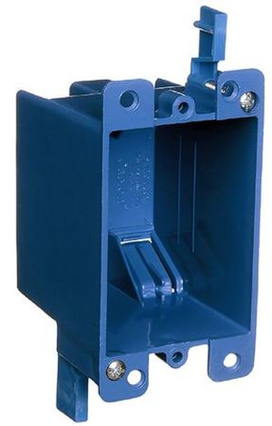
Inside the house I found the ideal location for a regular electrical outlet. It was centrally located so an extension cord plugged in could reach the refrigerator, microwave, etc., and a small stand-alone freezer in the next room. I measured the proper height above the floor to match other outlets in the room and used the outline of an old-work (retrofit) electrical box as a template to cut a hole in the drywall using only a box cutter utility knife. Be sure to use a level.
This location was near a light switch for the room. By carefully measuring, and locating the wall studs, I was able to find the same location from within the attic. I found the wire already in place leading to the light switch and determined where the wall studs must be. I drilled a hole down through the wall’s top-plate using a 3/4-inch auger bit, so as to avoid existing wiring and studs. My top-plate is double thickness (3 inches total).
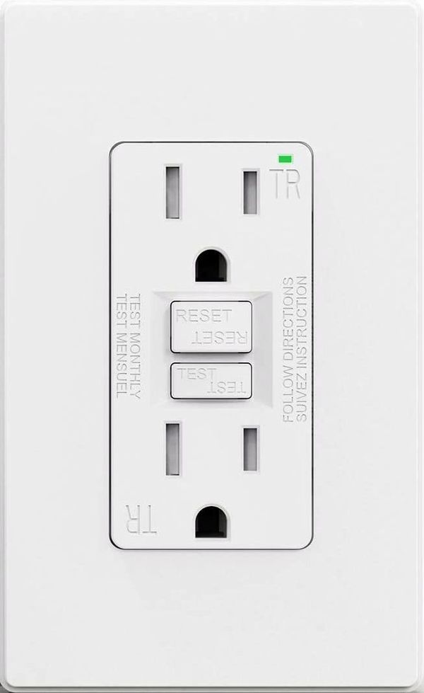
I used my metal fish tape in the attic to pull the wiring from the top of the outside wall at the soffit, over to the interior wall. Then it was easy enough to push the wire downward without using a fish tape. At the outlet in the kitchen, I connected a Ground Fault Circuit Interrupter (GFCI) outlet.
Although my portable generator has its own circuit protection, I thought it best to also install a GFCI. For one thing, the circuit is not connected to any household circuit breaker. I’m not an expert, but if there is a ground fault, perhaps the inside GFCI can handle it rather than having to go outside to reset the generator. And, the GFCI has an indicator light that shows whether the circuit is powered. That’s handy to ensure the generator hasn’t run out of fuel or the extension cord hasn’t come loose.
Since this is a retrofit, the wiring is not properly stapled to wall studs. Care must be taken not to penetrate the wall in these areas with a nail or fixture. The wire will be live only when connected to a running generator. If it is punctured, you may not realize it until the generator is connected and running.
Using the Generator
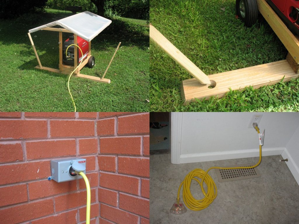
I locate the portable generator well out in the yard away from the house and any soffit vents to avoid accumulation of carbon monoxide gas in the garage, attic and living areas. I protect the generator from rain and high winds using a wooden platform to keep it off the ground. It has a frame and a roof of plastic sheeting. I attached cross braces to the platform to reduce the risk of tipping over during high winds.
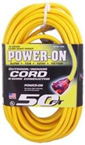
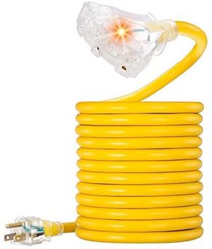
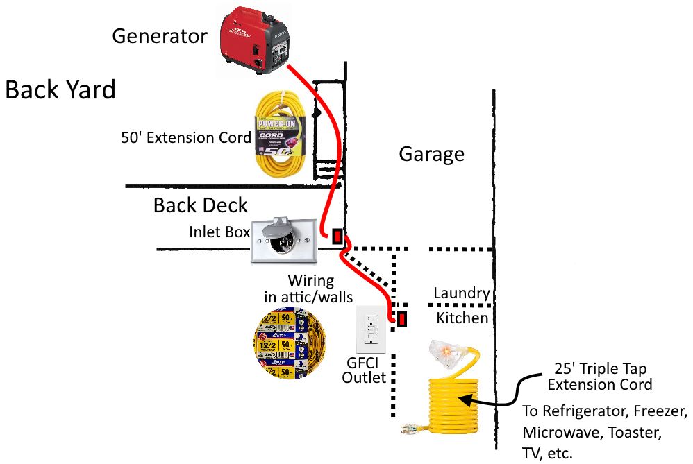
To use the inlet, I plug an outdoor-rated extension cord into the generator, and plug the other end into the inlet box. That activates the electrical outlet in the kitchen. I plug another extension cord into the kitchen outlet and use it to power appliances. Both extension cords have a lighted end to indicate power is active.
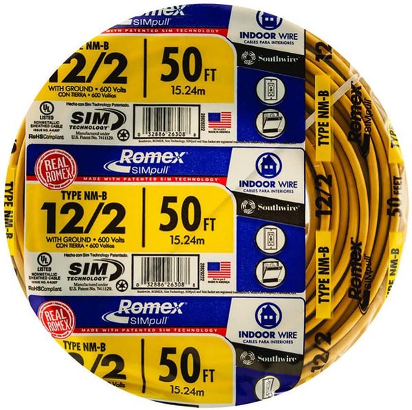
All wiring involved here is the same gauge as my normal household circuits. That is, I used 12 gauge, 2 conductor Romex for the interior wiring and both extension cords are 12/2 as well. In my case, the length of the household wiring I installed was 32 feet. I used that value to calculate voltage drop. If the generator extension cord is 50 feet and the kitchen extension cord is 25 feet, the total length is 107 feet. That means the voltage drop is 3.1% (3.7 volts) at 10 amps, and 4.6% (5.6 volts) at 15 amps, assuming the generator output is 120 volts. The total line length will affect which appliances you can use with a generator.
Depending on the generator, you can probably power only one or two appliances at a time. Most refrigerators and freezers have a high current draw when their compressor initially starts. You may want to turn off any “eco-throttle” or “reduced-throttle” feature on the generator when powering these appliances. Plug the refrigerator in and allow it to run for a time, then unplug it and plug in the freezer. Alternate periodically so each can maintain a cold temperature. I also use the extension cord for the microwave, toaster, coffee maker, TV, etc.
In summary, here is the plan for my portable generator inlet plug.
Below is my generator platform made of scrap lumber. The plastic sheeting on the roof can be easily replaced. I may devise something more sturdy with a tarp and bungee cords staked to the ground. The roof is removable, but also tilts lengthwise to allow access to the starter pull cord and fuel tank. A 2×4 cross brace on the ground keeps the generator upright in high winds. It is attached to the cart with a single large galvanized lag screw allowing it to pivot to get through doorways. It has two holes through which stakes are pounded at a slight angle to secure it to the ground.
Parts
Note: My generator is only 2000 Watts and therefore I used a regular straight blade inlet box. Most generator-specific inlet boxes on the market are rated for more wattage and therefore have a different blade configuration, and require different extension cords than I’ve listed here. Be sure to match the parts you need with your particular situation.
- Leviton 15A, 125V, 2-pole, 3-wire, weatherproof inlet, #4937 (a newer model #5278 is available https://amzn.to/3gGWGHC)
- Romex NM-B, 12/2 indoor electrical wire, 50 feet (https://amzn.to/3cQGe6v)
- ELEGRP 15 Amp GFCI Outlet, with LED Indicator, Wall Plate (https://amzn.to/3cPh0FC)
- Heavy Duty Extension Cord, SJTW, Lighted, Single tap, 12AWG, 15 Amps, 1875 Watts, 50 feet (https://amzn.to/2SHQG9i)
- Heavy Duty Extension Cord, SJTW, Lighted, Triple tap, 12AWG, 15 Amps, 1875 Watts, 25 feet (https://amzn.to/2TEqL2x)
Lowes has a good variety of outdoor electrical boxes. You can find a 1/2-inch PVC nipple (riser) at Home Depot. Home Depot also has a better selection of individual cold chisels.
